.svg?mw=64&hash=343d71fbdf234f1411db2920f2dff33c0dbd6231)

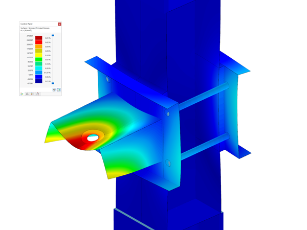
Steel Part of Connection
| Number of Nodes | 558 |
| Number of Lines | 399 |
| Number of Members | 40 |
| Number of Surfaces | 153 |
| Number of Load Cases | 4 |
| Number of Load Combinations | 2 |
| Total Weight | 0.418 tons |
| Dimensions (Metric) | 0.470 x 0.858 x 1.613 m |
| Dimensions (Imperial) | 1.54 x 2.81 x 5.29 feet |
| Program Version | 5.24.01 |


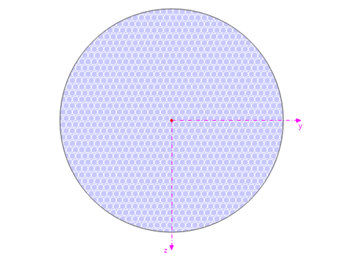


Get a better understanding of the stress distribution within member cross-sections by using clipping planes.

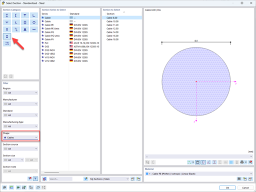
In RFEM, the oriented strand board (OSB) material is available for the USA and Canada. The material parameters are taken from the "Panel Design Specification manual".

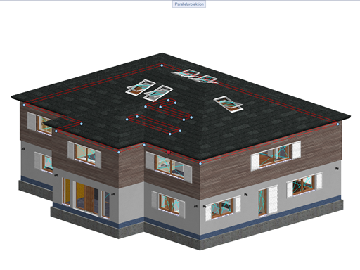
The "Bracing in Cells" function allows you to generate diagonal bracing with just a few clicks. You can find this feature under Tools → Generate Model – Members → Bracing in Cells.

In RFEM and RSTAB, you can visualize the flow field quantities of pressure, velocity, turbulence kinetic energy, and turbulence dissipation rate for the wind simulation.
The clipping planes are aligned with the respective wind direction.


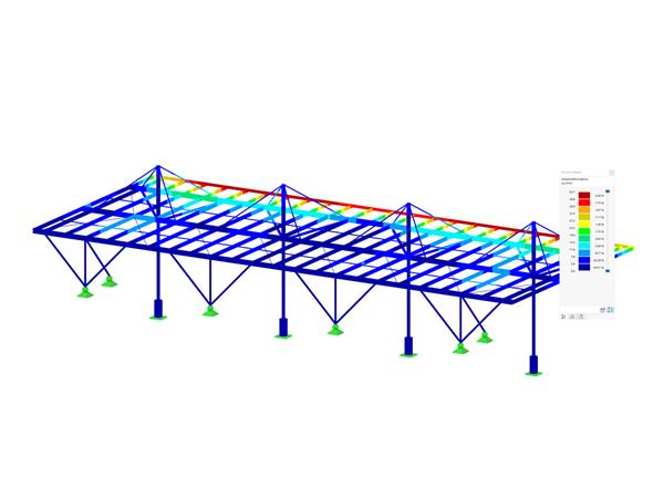
The new generation of 3D FEA software is used for the structural analysis of members, surfaces, and solids.
The Steel Design add-on performs the ultimate and serviceability limit state design checks of steel members according to various standards.
.png?mw=600&hash=49b6a289915d28aa461360f7308b092631b1446e)
The Steel Joints add-on for RFEM allows you to analyze steel connections using an FE model. The FE model is generated automatically in the background and can be controlled via the simple and familiar input of components.

The Torsional Warping (7 DOF) add-on allows you to consider cross-section warping as an additional degree of freedom.

The Nonlinear Material Behavior add-on allows you to consider material nonlinearities in RFEM for example, isotropic plastic, orthotropic plastic, isotropic damage).
The Structure Stability add-on performs stability analysis of structures. It determines critical load factors and the corresponding stability modes.

The Construction Stages Analysis (CSA) add-on allows for considering the construction process of structures (member, surface, and solid structures) in RFEM.
The Time-Dependent Analysis (TDA) add-on allows you to consider the time-dependent material behavior of members. The long-term effects, such as creep, shrinkage, and aging, can influence the distribution of internal forces, depending on the structure.
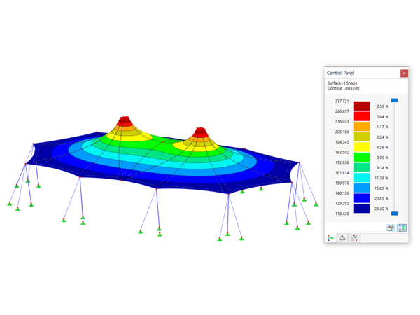
The Form-Finding add-on finds the optimal shape of members subjected to axial forces and tension-loaded surface models. The shape is determined by the equilibrium between the member axial force or the membrane stress and the existing boundary conditions.

The Modal Analysis add-on allows for the calculation of eigenvalues, natural frequencies, and natural periods for member, surface, and solid models.
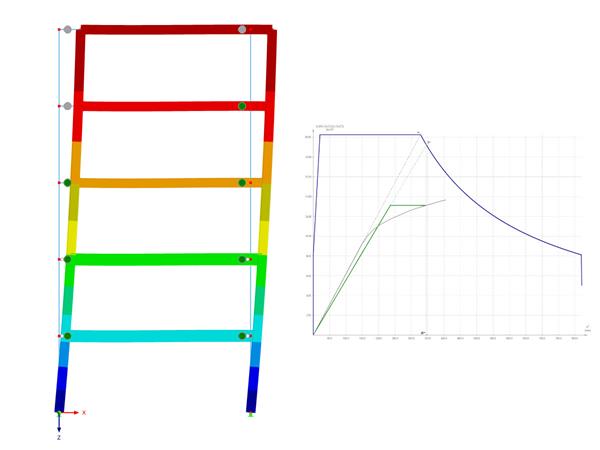
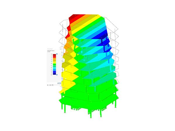
Using the Pushover Analysis add-on, you can analyze the seismic actions on a particular building, and thus assess whether the building can withstand an earthquake.

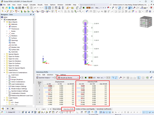
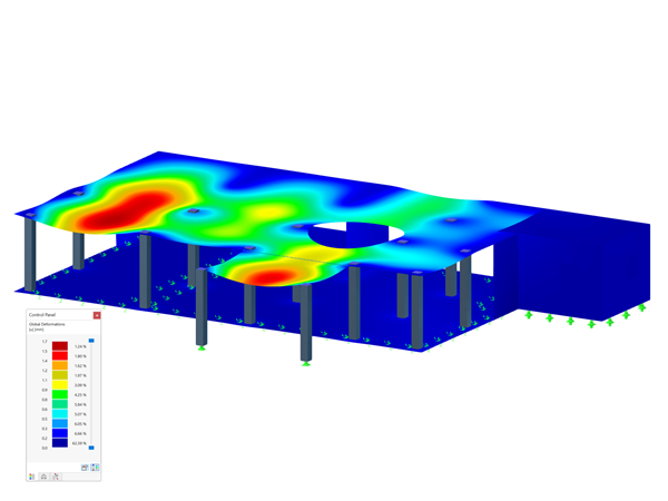
The Building Model add-on for RFEM allows you to define and manipulate a building using stories. The stories can be adjusted in many ways afterwards. The information about stories and the entire model (center of gravity) is displayed in tables and graphics.
The Stress-Strain Analysis add-on performs general stress analysis by calculating the existing stresses and comparing them with the limit stresses.

The modern 3D structural analysis and design program is suitable for the structural and dynamic analysis of beam structures as well as the design of concrete, steel, timber, and other materials.
The Steel Design add-on performs the ultimate and serviceability limit state design checks of steel members according to various standards.
The Structure Stability add-on performs the stability analysis of structures. It determines critical load factors and the corresponding stability modes.
The Stress-Strain Analysis add-on performs a general stress analysis by calculating the existing stresses and comparing them to the limit stresses.
The Torsional Warping (7 DOF) add-on allows for considering cross-section warping as an additional degree of freedom when calculating members.
The Modal Analysis add-on allows for the calculation of eigenvalues, natural frequencies, and natural periods for member, surface, and solid models.
Earthquakes may have a significant impact on the deformation behavior of buildings. A pushover analysis allows you to analyze the deformation behavior of buildings and compare them with seismic actions. Using the Pushover Analysis add-on, you can analyze the seismic actions on a particular building, and thus assess whether the building can withstand the earthquake.