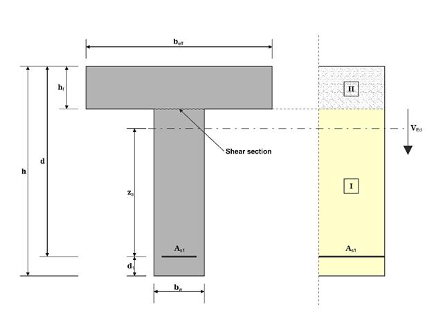
In this example, the shear at the interface between concrete cast at different times and the corresponding reinforcement are determined according to DIN EN 1992-1-1. The obtained results with RFEM 6 will be compared to the hand calculation below.
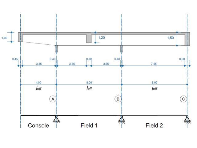
A reinforced concrete beam is designed as a two-span beam with a cantilever. The cross-section varies along the length of the cantilever (tapered cross-section). The internal forces, the required longitudinal and shear reinforcement for the ultimate limit state are calculated.
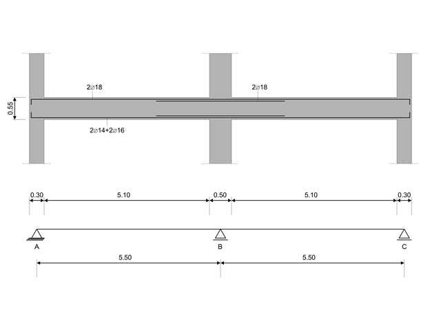
In this verification example, the capacity design values of shear forces on beams are calculated in accordance with EN 1998-1, 5.4.2.2 and 5.5.2.1 as well as the capacity design values of columns in flexure in accordance with 5.2.3.3(2). The system consists of a two span reinforced concrete beam with a span length of 5.50m. The beam is part of a frame system. The results obtained are compared with those in [1].
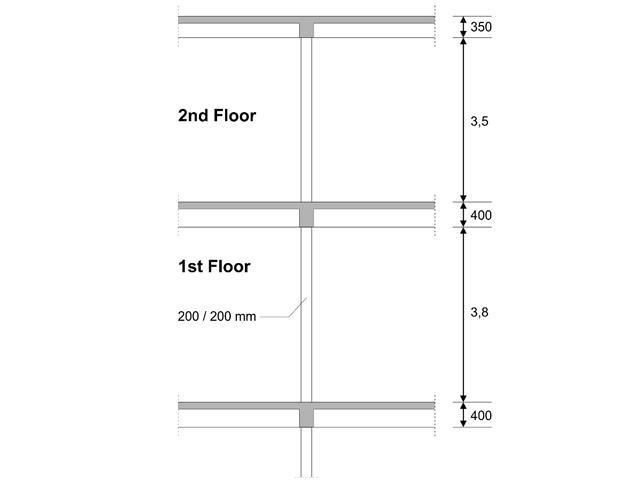
An inner column in the first floor of a three-story building is designed. The column is monolithic connected with the top and bottom beams. The fire design simplified method A for columns according to EC2-1-2 is than proofed and the results compared to [1].
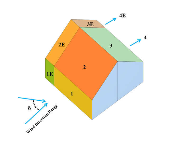
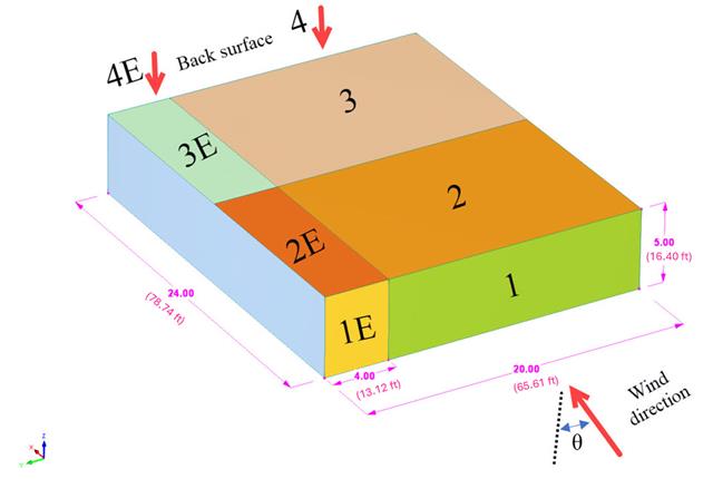
In the current validation example, we investigate wind pressure coefficient (Cp) for both main structural members (Cp,ave) and secondary structural members such as cladding or façade systems (Cp,local) based on NBC 2020 [1] and Japanese Wind Tunnel Data Base for low-rise building with 45 degree slope. The recommended setting for three-dimensional flat roof with sharp eaves will be described in the next part.
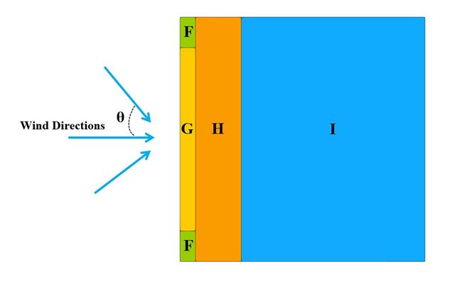
In the current validation example, we investigate wind pressure value for both general structural design (Cp,10) and local structural design such as cladding or façade systems (Cp,1) based on EN 1991-1-4 flat roof example [1] and Japanese Wind Tunnel Data Base . The recommended setting for three-dimensional flat roof with sharp eaves will be described in the next part.
In the current validation example, we investigate wind pressure coefficient (Cp) of flat roof and walls with ASCE7-22 [1]. In the section 28.3 (Wind loads - main wind force resisting system) and Figure 28.3-1 (load case 1), there is a table which shows Cp value for different roof angle.
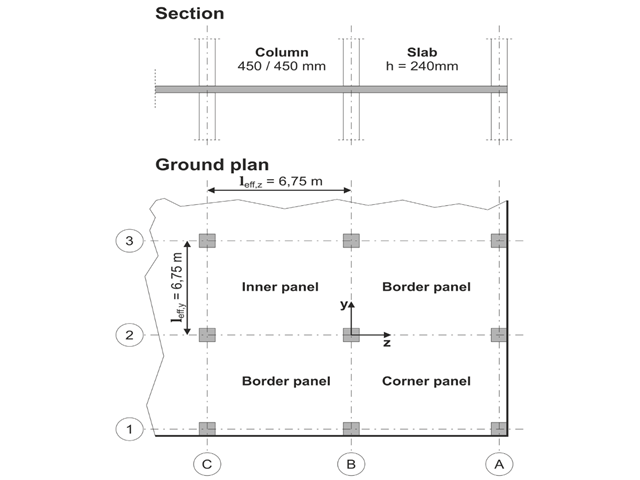
The model is based on the example 4 of [1]: Point-supported slab.
The flat slab of an office building with crack-sensitive lightweight walls is to be designed. Inner, border and corner panels are to be investigated. The columns and the flat slab are monolithically joined. The edge and corner columns are placed flush with the edge of the slab. The axes of the columns form a square grid. It is a rigid system (building stiffened with shear walls).
The office building has 5 floors with a floor height of 3.000 m. The environmental conditions to be assumed are defined as "closed interior spaces". There are predominantly static actions.
The focus of this example is to determine the slab moments and the required reinforcement above the columns under full load.
The model is based on the example 4 of [1]: Point-supported slab. The internal forces and the required longitudinal reinforcement can be found the in verification example 1022. In this example, punching is examined in the axis B/2.
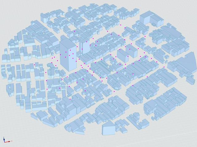
The Architectural Institute of Japan (AIJ) has presented a number of well-known benchmark scenarios of wind simulation.
The following article deals with "Case E - Building Complex in Actual Urban Area with Dense Concentration of Low-Rise Buildings in Niigata City".
In the following, the described scenario is simulated in RWIND& 2 and the results are compared with the simulated and experimental results by AIJ.
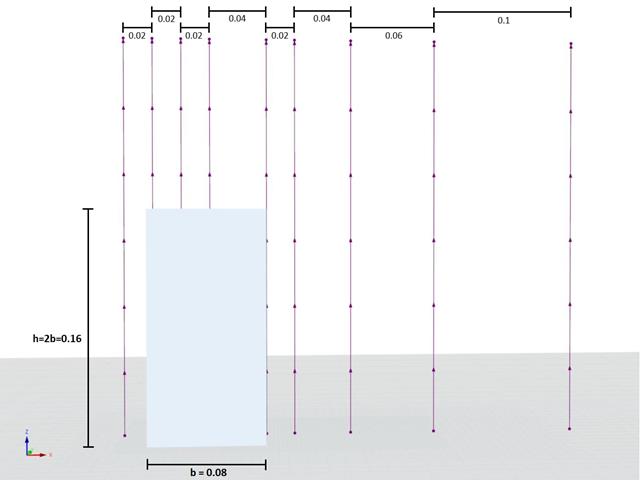
Das Architectural Institute of Japan (AIJ) hat eine Reihe an bekannten Benchmark-Szenarien für Windsimulation vorgestellt.
Der Nachfolgende Beitrag dreht sich dabei um den "Case A - high-rise building with a 2:1:1 shape".
Im Folgenden wird das beschriebene Szenario in RWIND2 nachgebildet und die Ergebnisse mit den simulierten und der experimentellen Resultate des AIJ verglichen.
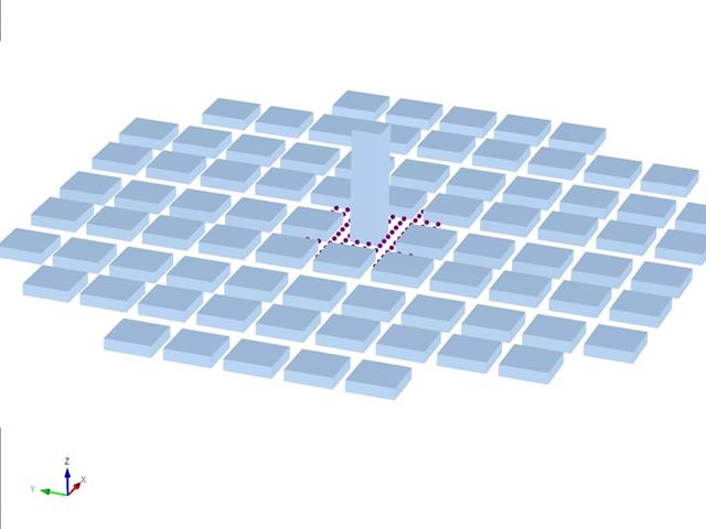
The Architectural Institute of Japan (AIJ) has presented a number of well-known benchmark scenarios of wind simulation.
The following article deals with "Case D - High-Rise Building Among City Blocks".
In the following, the described scenario is simulated in RWIND 2 and the results are compared with the simulated and experimental results by the AIJ.

Determine the required strengths and effective length factors for the ASTM A992 material columns in the moment frame shown in Figure 1 for the maximum gravity load combination, using LRFD and ASD.

An ASTM A992 W-shaped member is selected to carry a dead load of 30.000 kips and a live load of 90.000 kips in tension. Verify the member strength using both LRFD and ASD.

An ASTM A992 14×132 W-shaped column is loaded with the given axial compression forces. The column is pinned top and bottom in both axes. Determine whether the column is adequate to support the loading shown in Figure 1 based on LRFD and ASD.

An ASTM A992 W 24×62 beam with end shears of 48.000 and 145.000 kips from the dead and live loads, respectively, is shown in Figure 1. Verify the available shear strength of the selected beam, based on LRFD and ASD.

Using AISC Manual tables, determine the available compressive and flexural strengths and whether the ASTM A992 W14x99 beam has sufficient available strength to support the axial forces and moments shown in Figure 1, obtained from a second-order analysis that includes P-𝛿 effects.

A reinforced concrete slab inside a building is to be designed as a 1.0 m stripe with members. The floor slab is uniaxially spanned and runs through two spans. The slab is fixed on masonry walls with free-rotating supports. The middle support has a width of 240 mm and the two edge supports have a width of 120 mm. The two spans are subjected to an imposed load of category C: congregation areas.

A reinforced concrete column is designed for ULS at normal temperature according to DIN EN 1992-1-1/NA/A1:2015, based on 1990-1-1/NA/A1:2012-08. The design employs the nominal curvature method; see DIN EN 1992-1-1, Section 5.8.8. The addressed column is located at the edge of a 3-span frame structure, which consists of 4 cantilever columns and 3 individual trusses hinged to them. The column is subjected to the vertical force of the precast truss, snow and wind. The results are compared with the literature.

This verification example compares wind load calculations on a flat roof building using the ASCE 7-16 standard and using CFD simulation in RWIND Simulation. The building is defined according to the sketch and the inflow velocity profile taken from the ASCE 7-16 standard.