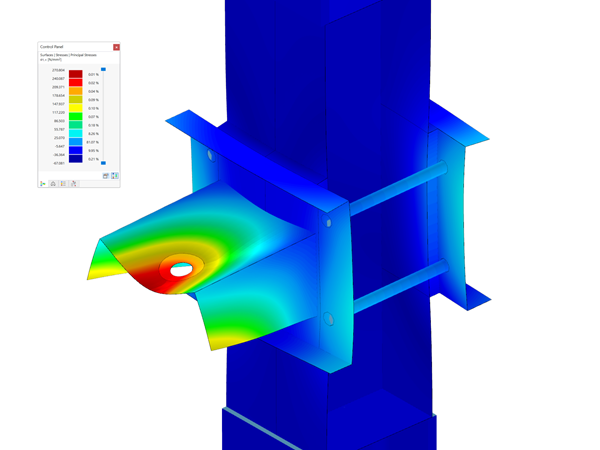
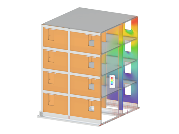
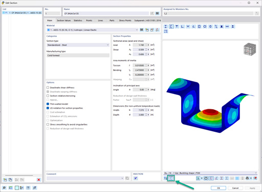
The classification of cross-sections according to EN 1993-1-1 using Table 5.2 is a simple method for designing the local buckling of cross-section parts. For cross-sections of cross-section class 4, it is then necessary to determine the effective cross-section properties according to EN 1993-1-5 in order to consider the influence of local buckling in the ultimate limit state designs.


.jpg?mw=350&hash=91f398b559b26a6ac36fd7ecdf5e395e7b9b856d)


.png?mw=600&hash=49b6a289915d28aa461360f7308b092631b1446e)