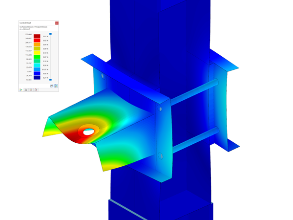
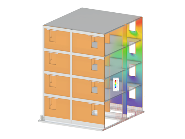
Due to the FE method, singularity points are displayed in a limited area as a concentration of the stress-dependent result values. They occur, among other things, at point-shaped load application areas in the model. This video shows the possibilities for dealing with such singularity locations.
T&T 011 | Singularities - At Concentrated Loads
Do you have any questions?
Singularities occur in a limited area due to the concentration of the stress-dependent result values. They are conditioned by the FEA methodology. In theory, the stiffness and/or the stress in an infinite size concentrate on an infinitesimally small area.
In RF-PUNCH Pro, you can perform the punching shear design on wall corners and wall ends. The basis for the design is the punching load, which is automatically determined from the RFEM internal forces in the connected surface. Since the surface internal forces from the RFEM calculation may be subject to the influence of singularity locations, this can also have a negative influence on the determined punching load at the wall corner or end. This article describes possible optimization options that you can use to minimize this unfavorable influence.
The averaged internal forces from the previously defined average regions can also be used for designing concrete surfaces. To do this, click [Details] in RF‑CONCRETE Surfaces, then select the corresponding check box. This function is accessible only if you previously defined an average region.
The boundary conditions of a plate support can be entered quickly as singular and line supports in the FEA software. However, if the flexibility of the supports is not considered when modeling the structure, it is often necessary to take a closer look at the support definitions during the design using stresses or the determination of the required reinforcement, at the latest.
In the ultimate configuration of the steel joint design, you have the option to modify the limit plastic strain for welds.
Using the "Base Plate" component, you can design base plate connections with cast-in anchors. In addition to plates and welds, the design analyzes the anchorage and the steel-concrete interaction.
In the "Edit Section" dialog box, you can display the buckling shapes of the Finite Strip Method (FSM) as a 3D graphic.
Do you have individual column sections and angled wall geometries, and need punching shear design for them?
No problem. In RFEM 6, you can perform punching shear design not only for rectangular and circular sections, but for any cross-section shape.
Recommended Products for You