Question
When calculating a connection using the FRAME‑JOINT Pro add-on module, a message appears saying that the value is out of the valid range (existing value: 160, minimum value 200). What does this message mean?
Answer:
This message is usually displayed when the member dimensions do not correspond.
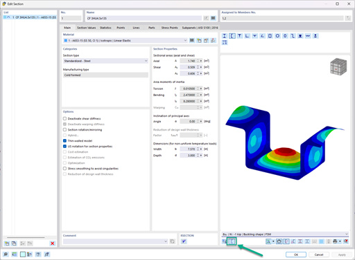
In the example model, the beam has a flange width of 200 mm, and the column support, of 160 mm.
This joint is not valid in the add-on module, as the flange width of the column should be at least as large as the flange width of the structural element to be connected. As soon as the cross-sections are defined according to this rule, the connection design can also be performed.
Do you have any questions?
The three types of moment frames (Ordinary, Intermediate, Special) are available in the Steel Design add-on of RFEM 6. The seismic design result according to AISC 341-22 is categorized into two sections: member requirements and connection requirements.
To evaluate whether it is also necessary to consider the second-order analysis in a dynamic calculation, the sensitivity coefficient of interstory drift θ is provided in EN 1998‑1, Sections 2.2.2 and 4.4.2.2. It can be calculated and analyzed using RFEM 6 and RSTAB 9.
The Steel Design add-on in RFEM 6 now offers the ability to perform seismic design according to AISC 341-16 and AISC 341-22. Five types of seismic force-resisting systems (SFRS) are currently available.
The three types of moment frames (Ordinary, Intermediate, Special) are available in the Steel Design add-on of RFEM 6. The seismic design result according to AISC 341-16 is categorized into two sections: member requirements and connection requirements.
When generating shear walls and deep beams, you can assign not only surfaces and cells, but also members.
In the ultimate configuration of the steel joint design, you have the option to modify the limit plastic strain for welds.
The "Base Plate" component allows you to design base plate connections with cast-in anchors. In this case, plates, welds, anchorages, and steel-concrete interaction are analyzed.
In the "Edit Section" dialog box, you can display the buckling shapes of the Finite Strip Method (FSM) as a 3D graphic.
Recommended Products for You