Question
What is the meaning of the warning message ER061) Minimum amplifier of design loads <1?
Answer:
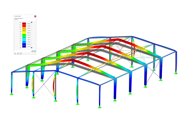
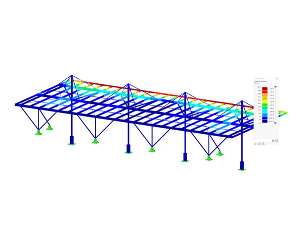
This message indicates that the critical load of the structure or the cross-section has been exceeded.The causes for this are very diverse. There are often insufficient lateral supports defined in the STEEL EC3 add-on module.
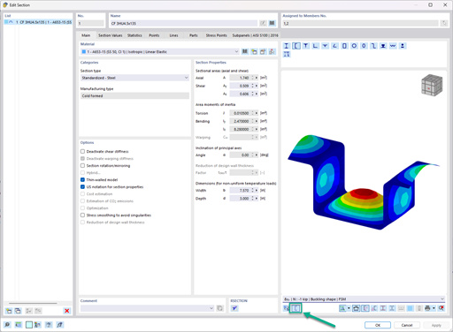
It is also possible that the used cross-sections or the structure itself cannot be calculated according to the general method in EC3. This FAQ provides more information about this issue.
Do you have any questions?
![Flexural Buckling Lines According to EN 1993-1-1](/en/webimage/010469/2987565/1_Knicklinien.png?mw=512&hash=9ad9ab1e9a7ae48f1bdadef46d94aff35c70c44c)
The RF‑/STEEL EC3 add-on module automatically transfers the buckling line to be used for the flexural buckling analysis for a cross-section from the cross-section properties. The assignment of the buckling line can be adjusted manually in the module input for general cross-sections in particular, as well as for special cases.
![System, Dimensions, and Cross-Sections](/en/webimage/014729/2950047/01-en.png?mw=512&hash=65e98cfe859ce35a3e3e9da47a0ef9335401520e)
This technical article deals with the design of structural components and cross-sections of a welded truss girder in the ultimate limit state. Furthermore, the deformation analysis in the serviceability limit state is described.
![Parameters for Member Load Calculation](/en/webimage/011737/2599315/01-en-png.png?mw=512&hash=e5b08a40fd9a5a16825be6182b3138f78627561e)
This technical article deals with the stability analysis of a roof purlin, which is connected without stiffeners by means of a bolt connection on the lower flange to have a minimum manufacturing effort.
![Design Loads and Imperfections for Structural Analysis](/en/webimage/011704/2599265/1626-5-en-us-png.png?mw=512&hash=fa62f0f4ca3d0d5ad78f02510d0c0f076500e2b9)
This technical article analyzes the effects of the connection stiffness on the determination of internal forces, as well as the design of connections using the example of a two-story, double-spanned steel frame.
![Feature 002820 | Limit Plastic Strain for Welds](/en/webimage/050344/3881226/1.png?mw=512&hash=9d7f6c198b6d4ae6ee8f2fa8bca75f85579e14c9)
In the ultimate configuration of the steel joint design, you have the option to modify the limit plastic strain for welds.
![Component "Base Plate"](/en/webimage/050345/3881657/1.png?mw=512&hash=9d7f6c198b6d4ae6ee8f2fa8bca75f85579e14c9)
The "Base Plate" component allows you to design base plate connections with cast-in anchors. In this case, plates, welds, anchorages, and steel-concrete interaction are analyzed.
![Feature 002807 | 3D Display of FSM Results](/en/webimage/049281/3861162/2024-05-01_10-32-55.png?mw=512&hash=2377d291bc20ac3d78d617b50c131614e99ac6f7)
In the "Edit Section" dialog box, you can display the buckling shapes of the Finite Strip Method (FSM) as a 3D graphic.
![Steel Design | Seismic Force-Resisting System Design Overview](/en/webimage/048507/3803346/seismic_steel.png?mw=512&hash=1c18a83f050e74601a7300444a0d77a0246a0e02)
- Design of five types of seismic force-resisting systems (SFRS) includes Special Moment Frame (SMF), Intermediate Moment Frame (IMF), Ordinary Moment Frame (OMF), Ordinary Concentrically Braced Frame (OCBF), and Special Concentrically Braced Frame (SCBF)
- Ductility check of the width-to thickness ratios for webs and flanges
- Calculation of the required strength and stiffness for stability bracing of beams
- Calculation of the maximum spacing for stability bracing of beams
- Calculation of the required strength at hinge locations for stability bracing of beams
- Calculation of the column required strength with the option to neglect all bending moments, shear, and torsion for overstrength limit state
- Design check of column and brace slenderness ratios
What could be the reason?
Recommended Products for You