Answer:
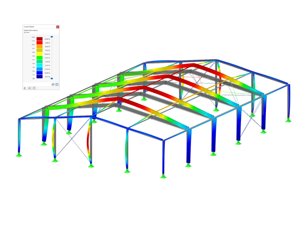
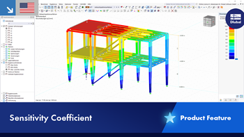
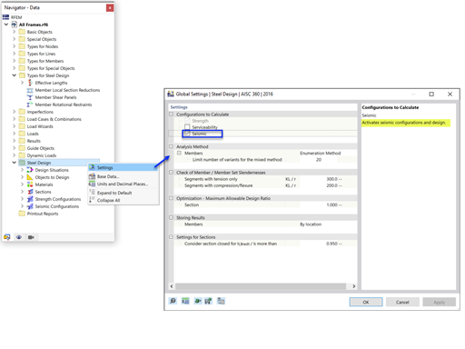
The Structure Stability add-on is not dependent on the settings made in the Steel Design add-on. It is a global stability analysis of the entire structure according to how the model is created. The setting of boundary conditions is only used for the design in the Steel Design add-on.
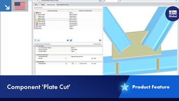
If you want the top flange to be supported, for example, we recommend using objects from Types for Members → Member Supports → Shear Panel. These objects are reflected in the results of the add-ons for dynamic and stability analysis.
In order to take into account the shear panel, it is necessary to activate this option of structural modification for the selected load cases or load combinations.
![FAQ 005465 | In the Steel Design add-on, I have set the boundary conditions in such a way that the I-beam flange is restrained against the horizontal displacement. [*S16592627*]](/en/webimage/048136/3767383/5465_en.png?mw=760&hash=3fa0e2d5dec02d22cf4756ab09b9e624d993ec5c)
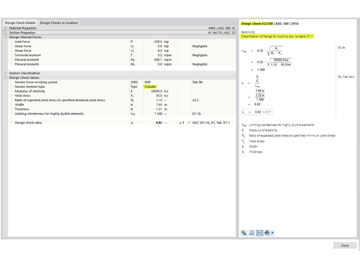
![FAQ 005465 | In the Steel Design add-on, I have set the boundary conditions in such a way that the I-beam flange is restrained against the horizontal displacement. [*S16592638*]](/en/webimage/048137/3767433/5465_2_en.png?mw=760&hash=2078ec58e86aa3d4769685d4fb8616d38d7120a6)
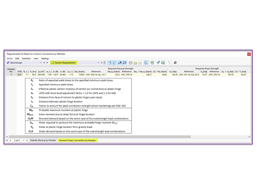
![FAQ 005465 | In the Steel Design add-on, I have set the boundary conditions in such a way that the I-beam flange is restrained against the horizontal displacement. [*S16592665*]](/en/webimage/048139/3767464/5465_3_en.png?mw=760&hash=cdf7ff4cd0c88bbaa3c267d4a8a484c5adc62291)


![FAQ 005465 | In the Steel Design add-on, I have set the boundary conditions in such a way that the I-beam flange is restrained against the horizontal displacement. [*S16592627*]](/en/webimage/048136/3767383/5465_en.png?mw=350&hash=5281e3653584e7b01523f89d814cc371edc6187c)
![FAQ 005465 | In the Steel Design add-on, I have set the boundary conditions in such a way that the I-beam flange is restrained against the horizontal displacement. [*S16592638*]](/en/webimage/048137/3767433/5465_2_en.png?mw=350&hash=14e6184ab7ac9dbf83f86a207b0ddc40726e711f)
![FAQ 005465 | In the Steel Design add-on, I have set the boundary conditions in such a way that the I-beam flange is restrained against the horizontal displacement. [*S16592665*]](/en/webimage/048139/3767464/5465_3_en.png?mw=350&hash=fc9dc71fd04da66baf2a8cf5681eb28267eda92a)


.png?mw=600&hash=49b6a289915d28aa461360f7308b092631b1446e)