Always keep track of your model. The model check quickly detects for you the input errors, such as overlapping members or identical nodes. You can automatically connect intersecting members during your input. Members can also be extended or divided graphically. The measure function allows you to determine lengths and angles of members and surfaces (only RFEM).

Do you have any questions?


Length: 00:00:50 min
Length: 00:58:00 min

Length: 00:55:53 min
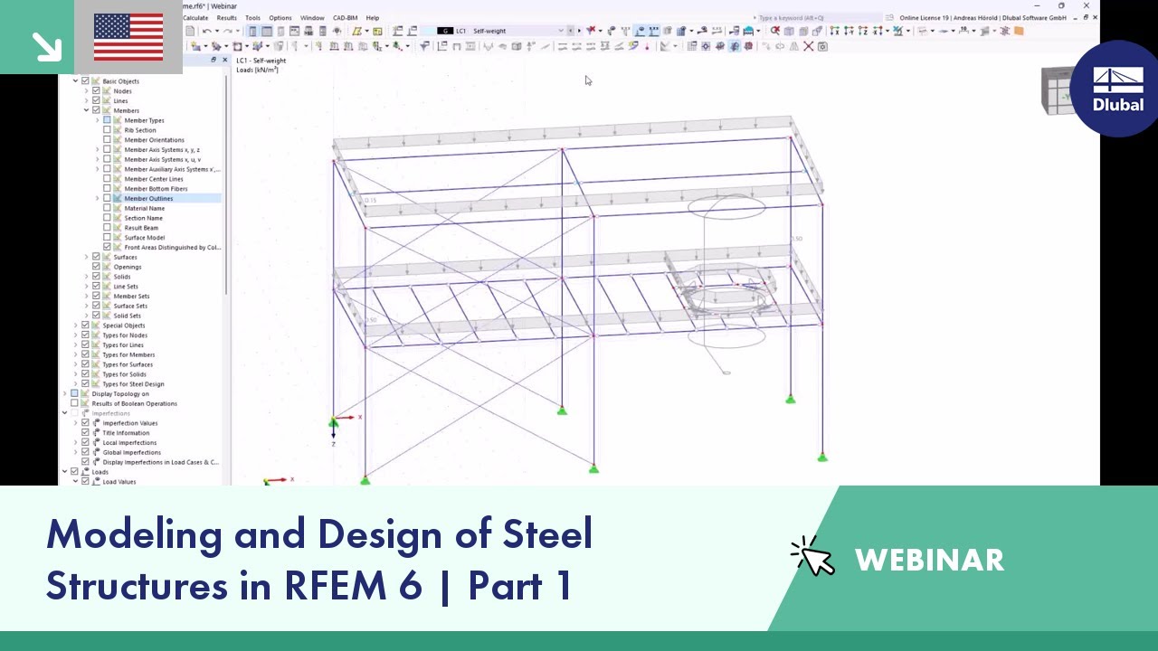
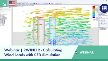
Length: 01:02:19 min
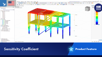
Length: 01:02:00 min
Length: 01:01:43 min

Length: 00:50:32 min
Length: 01:02:20 min
Length: 00:00:32 min


Defining the appropriate effective length is crucial in obtaining the correct member design capacity. For X-bracing that is connected at the center, engineers often wonder if the full end-to-end length of the member shall be used, or whether using half of the length to where the members are connected is sufficient. This article outlines the recommendations given by the AISC and provides an example on how to specify the effective length of the X-braces in RFEM.
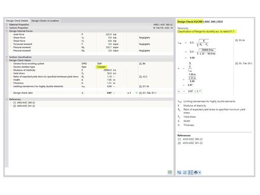
The three types of moment frames (Ordinary, Intermediate, Special) are available in the Steel Design add-on of RFEM 6. The seismic design result according to AISC 341-22 is categorized into two sections: member requirements and connection requirements.
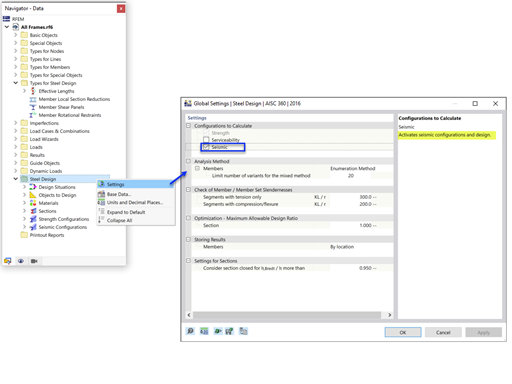
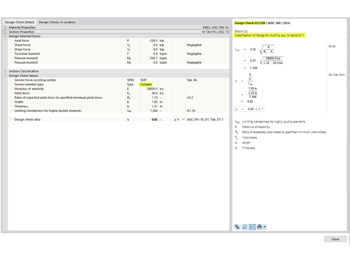
The Steel Design add-on in RFEM 6 now offers the ability to perform seismic design according to AISC 341-16 and AISC 341-22. Five types of seismic force-resisting systems (SFRS) are currently available.
The three types of moment frames (Ordinary, Intermediate, Special) are available in the Steel Design add-on of RFEM 6. The seismic design result according to AISC 341-16 is categorized into two sections: member requirements and connection requirements.


In the ultimate configuration of the steel joint design, you have the option to modify the limit plastic strain for welds.

The "Base Plate" component allows you to design base plate connections with cast-in anchors. In this case, plates, welds, anchorages, and steel-concrete interaction are analyzed.
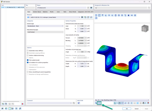
In the "Edit Section" dialog box, you can display the buckling shapes of the Finite Strip Method (FSM) as a 3D graphic.
- Design of five types of seismic force-resisting systems (SFRS) includes Special Moment Frame (SMF), Intermediate Moment Frame (IMF), Ordinary Moment Frame (OMF), Ordinary Concentrically Braced Frame (OCBF), and Special Concentrically Braced Frame (SCBF)
- Ductility check of the width-to thickness ratios for webs and flanges
- Calculation of the required strength and stiffness for stability bracing of beams
- Calculation of the maximum spacing for stability bracing of beams
- Calculation of the required strength at hinge locations for stability bracing of beams
- Calculation of the column required strength with the option to neglect all bending moments, shear, and torsion for overstrength limit state
- Design check of column and brace slenderness ratios
How can I reduce the calculation time for members with a nonlinear material model in RFEM 6 and RSTAB 9?
Why are the stresses of the structural analysis different from those calculated with the Stress-Strain Analysis add-on?
Is it possible to use the general method according to EN 1993‑1‑1, 6.3.4 to design structural components with an asymmetric cross-section in the Steel Design add-on for RFEM 6 or RSTAB 9?
How do I define a plastic hinge in RFEM 6?
How can I exchange data between RFEM 6 / RSTAB 9 and IDEA StatiCa?
How can I generate an area load on members via cells in RFEM 6 or RSTAB 9?

.jpg?mw=350&hash=91f398b559b26a6ac36fd7ecdf5e395e7b9b856d)


