- The European lateral-torsional buckling curve, regulated in the German National Annex to EN 1993, for example.
- The adaptation for biaxial bending according to a dissertation by Naumes.
- The interpolation between lateral buckling and lateral-torsional buckling.
Design of Sets of Members According to Eurocode 3
I cannot define effective lengths for the design of a set of members in STEEL EC3. Am I doing something wrong?
Answer:
In addition to the stability analysis in Section 6.3.1 through 6.3.3 of EN 1993‑1‑1 (Equivalent Member Method), the RF‑/STEEL EC3 add-on module provides the General Method according to Section 6.3.4 of EN 1993‑1‑1. The latter can be extended with the following options:
When designing sets of members according to the General Method, a window is available in Window "1.7 Nodal Supports – Sets of Members" where the nodal supports are displayed graphically on the set of members. This way, the General Method is a useful supplement to other design methods. It has proven itself particularly when designing tapers. It is not necessary to enter effective lengths in this method.
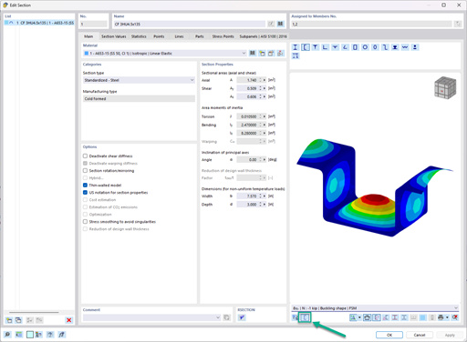
In the "Details" of the add-on module, you can select the method to be used for sets of members in the "Stability" tab (see Image 01).
The equivalent member method may only be used for straight sets of members with a uniform cross-section—that is, not for tapered joints. Therefore, use the preset General Method for members with a variable cross-section.
Author
Mr. Baumgärtel provides technical support for Dlubal Software customers.
Downloads
Do you have any questions?
Very small torsional moments in the members to be designed often prevent certain design formats. In order to neglect them and still perform the designs, you can define a limit value in RF‑/STEEL EC3 from which torsional shear stresses are taken into account.
The RF‑/STEEL EC3 add-on module automatically transfers the buckling line to be used for the flexural buckling analysis for a cross-section from the cross-section properties. The assignment of the buckling line can be adjusted manually in the module input for general cross-sections in particular, as well as for special cases.
This technical article deals with the design of structural components and cross-sections of a welded truss girder in the ultimate limit state. Furthermore, the deformation analysis in the serviceability limit state is described.
This technical article deals with the stability analysis of a roof purlin, which is connected without stiffeners by means of a bolt connection on the lower flange to have a minimum manufacturing effort.
In the ultimate configuration of the steel joint design, you have the option to modify the limit plastic strain for welds.
The "Base Plate" component allows you to design base plate connections with cast-in anchors. In this case, plates, welds, anchorages, and steel-concrete interaction are analyzed.
In the "Edit Section" dialog box, you can display the buckling shapes of the Finite Strip Method (FSM) as a 3D graphic.
- Design of five types of seismic force-resisting systems (SFRS) includes Special Moment Frame (SMF), Intermediate Moment Frame (IMF), Ordinary Moment Frame (OMF), Ordinary Concentrically Braced Frame (OCBF), and Special Concentrically Braced Frame (SCBF)
- Ductility check of the width-to thickness ratios for webs and flanges
- Calculation of the required strength and stiffness for stability bracing of beams
- Calculation of the maximum spacing for stability bracing of beams
- Calculation of the required strength at hinge locations for stability bracing of beams
- Calculation of the column required strength with the option to neglect all bending moments, shear, and torsion for overstrength limit state
- Design check of column and brace slenderness ratios
What could be the reason?
Recommended Products for You